Rungs 5 6 and 7 Are Not Scanned by the Processor When Rung Has Logic Continuity
In this lesson we're going to go through a basic seal in instruction used to "hold" in an output such as you would use for a start stop motor control.
1. Before you start this lesson, you will need to make one change to the wiring of your trainer. In the previous lesson,RsLogix 500 - Electrical Contacts - Normally Open and Normally Closed Contacts, you learned the difference between normally open and normally closed contacts. Change the wiring of Button 3 so that it is connected to the PLC through a normally closed contact instead of a normally open contact. If you do this correctly, I:0/2 on the trainer will be ON when Button 3 is not pressed.
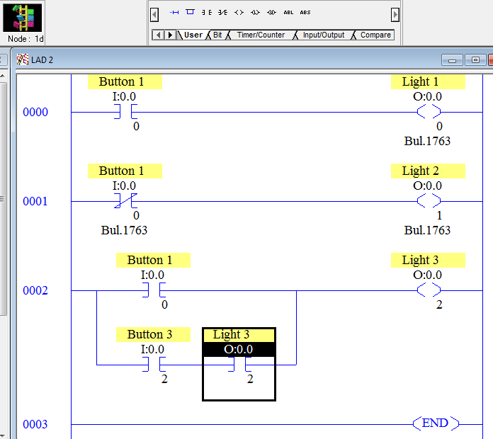
2. Open up the program you were using in theRsLogix 500 Basic ON/OFF Control XIC XIO OTE and add Rung 2 to the bottom of it as shown below.
3. In this lesson, Button 1 will be our Start Button and Button 3 will be our Stop Button. To do this, right click the text of Button 1 in one of the instructions and select "Edit Description".

4. You will see two fields. The description and a symbol.
-
The description allows you give a detailed explanation of what the value represents.
-
The symbol on the other hand is limited to 20 characters but can be used to enter an address in an instruction.
Instead of typing I:0/0 when addressing an XIC, we can simply type "START". As nice of a feature as this is, hold off on using it until you have a firm understanding of the data tables in the PLC. Symbols are great time savers when programming, but many beginners use them because they struggle to navigate and understand the data tables.

5. Let's change Button 3's text a different way. Double click on the "I1 - INPUT" data table, next click on I:0/3's data box, then double click on the description, and change it to "Stop Button" and click OK.


7. Momentarily pressing Button 1 will turn on Light 3. When you let off of Button 1, Light 3 continues to be ON. Momentarily pressing Button 3 turns off Light 3. Does yours work like that? If not, go back and correct any errors then let's walk through the program flow below.
Here is our program flow image which is very similar to the one you saw in theRsLogix 500 Basic ON/OFF Control XIC XIO OTE lesson. I have omitted rungs 0 and 1 so we can concentrate on rung 2.

Let's go through the program flow of the PLC while neither button is pressed.
1. The PLC updates its input data table values based off of the physical states of the inputs. In the last example of program flow we said since the button was "pressed" it wrote a "1" to the data box. Now that we have added normally closed contacts, this would be confusing. The best way to determine whether or not the input is on is to ask yourself, "Do I have current?". Some people will say "Do I have voltage" but "Do I have current" is more thorough because it says:
-
I have power at my switch.
-
My switch contact is allowing current to flow.
-
I have a continuous path from my switch to my input terminal.
-
My input module is good.
-
I have a wire connected to my input modules common to complete the current path.
You would be surprised the number of times asking yourself "Do I have current" will lead you to the problem with your program. In our case right now I/0 does not have current so it has a "0" in I:0/0's data box and I/2 has current so it has a "1" in I:0/2's data box.
2. The PLC begins executing the ladder logic with the very left instruction of rung 0. The XIC tells the PLC to check for a "1" in the I:0/0 data box.
3. The PLC looks in the I:0/0 data box and sees there is a "0" in the I:0/0 data box.
4. This instruction was looking for a "1" and found a "0", the instruction is evaluated as FALSE.
5. This is a Branch. We didn't give you a lot of instructions on how to do this so CONGRATULATIONS on getting it properly inserted. When the PLC comes to the end of the branch or the right side, it then goes back to the beginning of the branch or left side and continues down the next path. Even though you may see this as a parallel path, the PLC still has a methodical way of executing instructions one at a time.
6. The XIC tells the PLC to check for a "1" in the I:0/2 data box. The PLC does not care whether there is a normally open or normally closed contact connected to this instruction.
7. The PLC looks in the I:0/2 data box and sees there is a "1" in the I:0/2 data box.
8. This instruction was looking for a "1" and found a "1", the instruction is evaluated as TRUE.
9. The XIC tells the PLC to check for a "1" in the O:0/2 data box. The PLC does not care whether it is looking at an input, output, binary, or any other data table type. To the PLC it is just another box.
10. The PLC looks in the O:0/2 data box and sees there is a "0" in the O:0/2 data box.
11. This instruction was looking for a "1" and found a "0", the instruction is evaluated as FALSE. But this is the second instruction on this line so the PLC so whether the rung is true of false at this point depends on step 8. If the first instruction is true and this instruction is true then the outcome will be true. If either instruction is false then the outcome will be false. So in this case the PLC will pass FALSE to the next instruction.
12 and 13. The PLC has two paths to evaluate to determine if the OTE instruction should execute with true of false conditions. If either path off of the branch is true then the OTE will be true. If all branches are false, such as this time, then the OTE will be false. Remember, a false OTE still writes a 0 so the PLC will write a "0" to the O:0/2 data box.
14. The last rung of the routine has an END instruction. It signals the PLC to proceed to update it's output instructions.
15. The PLC updates it's outputs based off of the output data table. If there is a "0" in an output data box then it turns the output off, if there is a "1" in an output data box then it turns the output on.
16. The PLC does it's overhead then returns to step 1.
Let's go through it with the start button pressed. You already know that Light 3 will turn ON, but make sure you understand the program flow leading up to it.

1. The PLC updates its input data table values based off of the physical states of the inputs. I/0 has current so it has a "1" in I:0/0's data box and I/2 has current so it has a 1 in I:0/2's data box.
2. The PLC begins executing the ladder logic with the very left instruction of rung 0. The XIC tells the PLC to check for a "1" in the I:0/0 data box.
3. The PLC looks in the I:0/0 data box and sees there is a "1" in the I:0/0 data box.
4. This instruction was looking for a "1" and found a "1", the instruction is evaluated as TRUE.
5. This is the end of the branch so the PLC will go back to the beginning of the branch and continue down the next path.
6. The XIC tells the PLC to check for a "1" in the I:0/2 data box.
7. The PLC looks in the I:0/2 data box and sees there is a "1" in the I:0/2 data box.
8. This instruction was looking for a "1" and found a "1", the instruction is evaluated as TRUE.
9. The XIC tells the PLC to check for a "1" in the O:0/2 data box.
10. The PLC looks in the O:0/2 data box and sees there is a "0" in the O:0/2 data box.
11. This instruction was looking for a "1" and found a "0", the instruction is evaluated as FALSE. Even though step 8 was TRUE, this will make the PLC pass a FALSE to the next instruction.
12 and 13. The first branch was TRUE and the second branch was FALSE so the OTE will be TRUE. The true OTE will write a "1" to the O:0/2 data box.
14. The last rung of the routine has an END instruction. It signals the PLC to proceed to update it's output instructions.
15. The PLC updates it's outputs based off of the output data table. If there is a "0" in an output data box then it turns the output off, if there is a "1" in an output data box then it turns the output on.
16. The PLC does it's overhead then returns to step 1.
Let's go through it with the start button released and Light 3 ON. Make sure you understand how the "Seal in" works.

1. The PLC updates its input data table values based off of the physical states of the inputs. I/0 does not have current so it has a "0" in I:0/0's data box and I/2 has current so it has a "1" in I:0/2's data box.
2. The PLC begins executing the ladder logic with the very left instruction of rung 0. The XIC tells the PLC to check for a "1" in the I:0/0 data box.
3. The PLC looks in the I:0/0 data box and sees there is a "0" in the I:0/0 data box.
4. This instruction was looking for a "1" and found a "0", the instruction is evaluated as FALSE.
5. This is the end of the branch so the PLC will go back to the beginning of the branch continue down the next path.
6. The XIC tells the PLC to check for a "1" in the I:0/2 data box.
7. The PLC looks in the I:0/2 data box and sees there is a "1" in the I:0/2 data box.
8. This instruction was looking for a "1" and found a "1", the instruction is evaluated as TRUE.
9. The XIC tells the PLC to check for a "1" in the O:0/2 data box.
10. The PLC looks in the O:0/2 data box and sees there is a "1" in the O:0/2 data box.
11. This instruction was looking for a "1" and found a "1", the instruction is evaluated as TRUE. Since step 8 was also TRUE, this PLC will pass TRUE to the next instruction.
12 and 13. The first branch was FALSE and the second branch was TRUE so the OTE will be TRUE. The true OTE will write a "1" to the O:0/2 data box.
14. The last rung of the routine has an END instruction. It signals the PLC to proceed to update it's output instructions.
15. The PLC updates it's outputs based off of the output data table. If there is a "0" in an output data box then it turns the output off, if there is a "1" in an output data box then it turns the output on.
16. The PLC does it's overhead then returns to step 1.
Let's go through it one final time to show how it stops. Light 3 is ON, the Start Button is not pressed, and you press the Stop Button.

1. The PLC updates its input data table values based off of the physical states of the inputs. I/0 does not have current so it has a "0" in I:0/0's data box and I/2 does not have current so it has a "0" in I:0/2's data box.
2. The PLC begins executing the ladder logic with the very left instruction of rung 0. The XIC tells the PLC to check for a "1" in the I:0/0 data box.
3. The PLC looks in the I:0/0 data box and sees there is a "0" in the I:0/0 data box.
4. This instruction was looking for a "1" and found a "0", the instruction is evaluated as FALSE.
5. This is the end of the branch so the PLC will go back to the beginning of the branch continue down the next path.
6. The XIC tells the PLC to check for a "1" in the I:0/2 data box.
7. The PLC looks in the I:0/2 data box and sees there is a "0" in the I:0/2 data box.
8. This instruction was looking for a "1" and found a "0", the instruction is evaluated as FALSE.
9. The XIC tells the PLC to check for a "1" in the O:0/2 data box.
10. The PLC looks in the O:0/2 data box and sees there is a "1" in the O:0/2 data box.
11. This instruction was looking for a "1" and found a "1", the instruction is evaluated as TRUE. Since step 8 was false, the PLC will pass FALSE to the next instruction despite this one being TRUE.
12 and 13. The first branch was FALSE and the second branch was FALSE so the OTE will be FALSE. The false OTE will write a "0" to the O:0/2 data box.
14. The last rung of the routine has an END instruction. It signals the PLC to proceed to update it's output instructions.
15. The PLC updates it's outputs based off of the output data table. If there is a "0" in an output data box then it turns the output off, if there is a "1" in an output data box then it turns the output on.
16. The PLC does it's overhead then returns to step 1.
One important note. When we wrote this lesson we removed rungs 0 and 1 for simplicity since we wanted to focus on the program flow of rung 2. While it didn't have an affect on this program, beginners often focus on a single rung when trying to troubleshoot their program instead of looking at the big picture. Don't forget to look for other things that may be writing to your output when troubleshooting.
Source: https://twcontrols.com/lessons/rslogix-500-training-seal-in-rung-and-plc-scan-explanation
0 Response to "Rungs 5 6 and 7 Are Not Scanned by the Processor When Rung Has Logic Continuity"
Post a Comment